How I built my IoT infrastructure
My father Peter is a passionate beekeeper [see honig.spreitzer.at] having some hives in his garden and is always interested about what’s going on in the houses of his many girls. Besides many things there is especially one indicator that is of high interest for a beekeeper: the current weight of the hive. Having some measurements over time gives you insights of how a bee colony develops.
So he had put some hives already on mechanical scales but – of course – he could only evaluate the weight sporadically when he was caring for his bees.

He soon heard about professional hive-scales that are continuously checking the weight and sending the data to some endpoint, may it be SMS, web or an SD-Card. But these professional beehive-scales are way too expensive for a hobby beekeeper. Doing some research on the web you quickly learn about a lot of projects where beekeepers from all over create their own beehive-scales. One project – beelogger.de – caught my interest and so I started experimenting with their solution. But quite soon I found out that it was not exactly the solution my father needed. E.g. he does not need to power the system of a battery and/or photovoltaic cells (power-line is nearby) or does not need to transmit the data via mobile (garden has wifi coverage).
Having played around a lot with Arduino and ESP8266 microcontrollers I started developing my own idea of how such a beehive-scale should work.
This blog post gives you an overview of how I designed the whole system – from automatically collecting the hive data to visualising it in an appropriate and generic manner and sending alert emails when special events in data occur. You wonder why the project title “HiveSUMMary” is written like that? Well, that is because SUMMen in german means “to hum”. :-)
Overview

My beehive-scale ecosystem basically consists of three independent parts:
- Beehive-Scale hardware
- Weighting Cell + ESP8266 microcontroller – one for each hive
- IoT Device Manager
- PHP script to provide a static endpoint for each ESP8266 and provides a basic gateway to send the received data to my IoTLog instance
- IoTLog
- WordPress Plugin to manage data storage, visualisation, monitoring and alerting
As you can see in the names of “IoT*” I did not design the system to be “just” a beehive-scale system but to be my generic idea of an IoT (“Internet of Things”) system and managing the hive-scales being just the first use-case for it. Over the time I also started using it for lots of other sensors – e.g.
- HiGrow moisture sensor
- MQ-X gas sensors
- ESP32-Cam
- personal weather station
- many more to come
Lots of ideas are borrowed from microservice architecture and other well-known (software) development patterns. Most parts are designed to be stateless which keeps them easily adoptable and flexible. Data is mostly transferred as JSON for the same reason.
Basically the system should just provide a framing to solve the problem of collecting, storing, visualising, evaluating and reacting to data.
Beehive-Scale Hardware
ESP8266-12 + HX711 + Weighting Cell

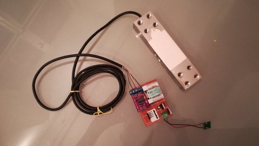
First working prototype of the PCB + weighting cell
I based the hardware for the hive-scale on the dirt-cheap ESP8266 microcontroller. It has lots of GPIO ports and integrated WiFi capabilities. As it can be programmed via the Arduino IDE with its big ecosystem of libraries for various sensors it is a good choice for my requirements.
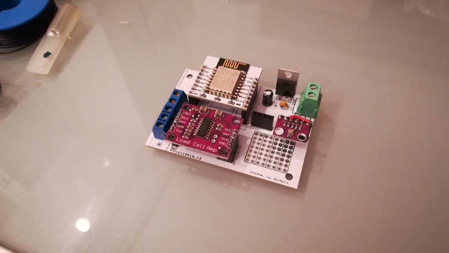
The basic hardware setup consists of the following parts:
- ESP8266-12 microcontroller, ~2 Eur
- HX711 Load Cell Amp, ~1 Eur
- 200kg weighting sensor load cell, ~10 Eur
- LD1117 3,3V Voltage Regulator, ~0.2 Eur
- Some screw terminal blocks and capacitors
Additionally the firmware also supports the following sensors:
- DS18B20 temperature sensor [1-wire], ~2 Eur
- BME280 temperature, air pressure, humidity sensor [i2c], ~3 Eur
- BMP280 temperature, air pressure sensor [i2c], ~1 Eur
- BH1750 light sensor [i2c], ~2 Eur

BeeHive-Scales collecting data

First tries to calibrate the BeeHive-Scale 
Iron frame holding the weighting cell
The principal functionality of taking the measurements is as follows: The ESP8266 microcontroller starts up, connects to one of the predefined WiFi networks and initialises any connected (and supported) sensors. Then it takes all the measurements, posts them to the IoT Device Manager and goes into deep sleep mode. After another 15 minutes the ESP8266 wakes up and performs all the actions again.
Firmware features
- Capable of various sensors – whatever is connected is initialised and evaluated – no reprogramming needed if sensor-setup is changed
- Scale calibration: ability to calculate scale factor and offset values remotely
- Secure requests via https
- If IoT Device Manager after a request responds with stayawake-flag the ESP8266 stays awake for 10 minutes.
During this time it- allows OTA updates via Arduino IDE
- runs a webserver and responds to the following endpoints
- http://ip [Status]
- http://ip/measure [measure and view values]
- http://ip/calibrate [start weighting cell calibration]
- http://ip/restart [reboots the ESP8266]
Arduino Build Script
I like the Arduino IDE for its simplicity – however as a professional software developer I was missing some important features to automate things – especially regarding building and compiling the source files. So after some research (see here) I learned that the Arduino IDE already has a CLI built in. The basic way to build the sources for the ESP8266 from the command line is as follows:
#!/bin/sh
rm *.bin
ARDUINO_BIN=/Applications/Arduino.app/Contents/MacOS/Arduino
$ARDUINO_BIN --verify zwt_beescale_esp8266.ino --board esp8266:esp8266:generic:eesz=4M2M --pref build.path=build
This script
- removes any previous build (“rm *.bin”)
- builds (“verify”) the given zwt_beescale_esp8266.ino.generic.ino file against ESP8266 with an EEPROM size of 4M2M and saves the compiled result into zwt_beescale_esp8266.ino.generic.bin
Note: This is basically the same as using the Arduino IDE feature Sketch -> Export compiled binary.
OTA Update Bash Script
To upload the compiled binary to any OTA-enabled ESP8266 from the command line I use the following script named flash_ota.sh
#!/bin/sh
ip=$1
path=$2
password="pwd-used-for-OTA"
python /Users/YOUR_USER_NAME/Library/Arduino15/packages/esp8266/hardware/esp8266/2.6.3/tools/espota.py -d -r -i $ip -p 8266 --auth="$password" -f "$path"
Sample usage to flash compiled binary to ESP8266 currently having IP 10.0.0.67:
> ./flash_ota 10.0.0.67 /PATH/TO/YOUR/PROJECT/zwt_beescale_esp8266.ino.generic.binNote: Again you can accomplish the same in the Arduino IDE: Select your currently online ESP8266 via Tools -> Port and then press the upload button.
The reason I still wanted bash scripts to do these jobs is that I can freely combine any tasks – e.g. I have scripts that
- build and upload the compiled binary in one step
- build and copy the compiled binary via VPN to the remote RaspberryPI at my fathers place. The RaspberryPI then starts the upload of the binary to the ESP8266 which – for the RaspberryPi – is in the local network.
Note: The step of delegating the OTA-uploading to the RaspberryPI was necessary as I did not manage to get OTA updates working via my openVPN connection {Please drop me a line if you were able to do so over a VPN}.
Custom PCB
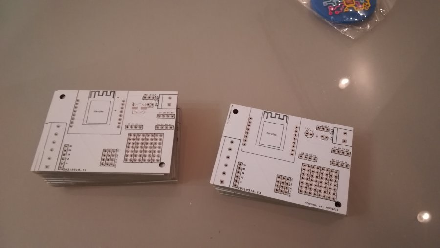
The first few devices I created manually on prototyping boards but that took me about two hours per board and is prone to failures while assembling.
So I started to experiment with Fritzing to design a PCB and had it produced. Now it just takes me some minutes to assemble a new hardware unit. Furthermore I designed the board with flexibility in mind so I can use it for whatever other purpose that comes to my mind.

My first fully functioning PCB – so proud :-)
Flashing firmware to ESP8266-12 via Serial
My current PCB does have a serial connection for debugging but is not prepared to put the ESP8266 into flash/upload mode. For that reason I built another board I just use for uploading the firmware. Such a board needs to pull
- GPIO-0 to Ground
- GPIO-2 to High and
- GPIO-15 to Ground.
For more information on bootloader modes search for “ESP8266-12 modes” or check out this guide.
Software: IoT Device Manager

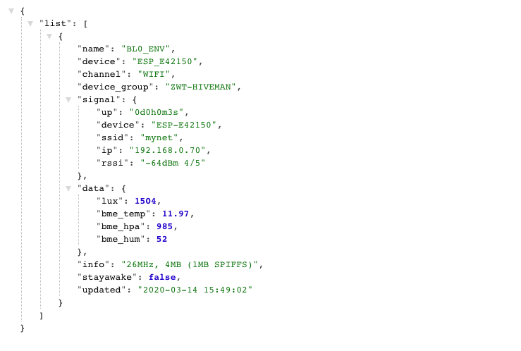
Buffered (meta) data of environmental sensor
Though I’m more into “real” object-oriented programming languages like Java I decided to implement the software-side in PHP as you can easily deploy it to most (shared) hosters and I just did not want to have the hassels of operating and an instance of a Java Application Server.
As IoT is highly distributed by nature I soon found out that I needed some sort of managing layer for all the devices. The basic idea of this IoT Device Manager is to have a known static entry point where each IoT Device (every ESP8266 in my case) can post data to. This layer then knows for each device what to do with the collected data. In my case I just forward it to my IoTLog but I could also easily just define any other action that should be taken.
Key features
- Provides an endpoint for each IoT Device to post data to
- Handles authentication of the devices
- Each device has assigned a name, channel and device group
- Decides what to do with the received data (forward, web hook, email)
- Buffers latest (meta) data
- last time online
- (local) IP address – useful when updating ESP firmware OTA
- RSSI (signal strength) of WiFi
- SSID of WiFi
- Data (very useful for debugging :-)
- LoRa integration: The Idea is to have any LoRa device send data which is received by a dedicated ESP8266 and proxied to this IoT Device Manager. Also handles AES-CBC decryption (see my previous post)
- REST-API: query for devices by device group, name, channel
- In that way it can act as sort of name service to find out the current IP of a device that was assigned via DHCP.
- Stay-Awake: As my ESP8266 microcontrollers are mostly always in deep sleep to save energy I normally can not update their firmware over-the-air (OTA). For this reason I can flag a device to stay awake the next time it sends me data. When this happens I receive an email that the device is now reachable and I can update its firmware. Because I also collect meta data I know its latest IP address. With some bash script magic (see above) I even managed to update the ESPs over a VPN-tunnel – cool ey?
- Backed by just one database table
Software: IoTLog

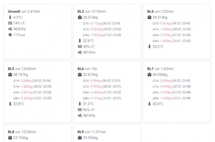
Report cards -insights into your data
Again I decided to write this functionality in PHP but taking it even further I implemented it as a WordPress Plugin. Using WordPress as your development framework let’s you reuse a lot of features – Rendering Webpages, Data Storage via (my)SQL, deploying your plugin and so on. And just think about how easy it is to have an instance of WordPress Page – most hosters even provide one-click installers. – Just install the IoTLog plugin and the platform is up and running :-)

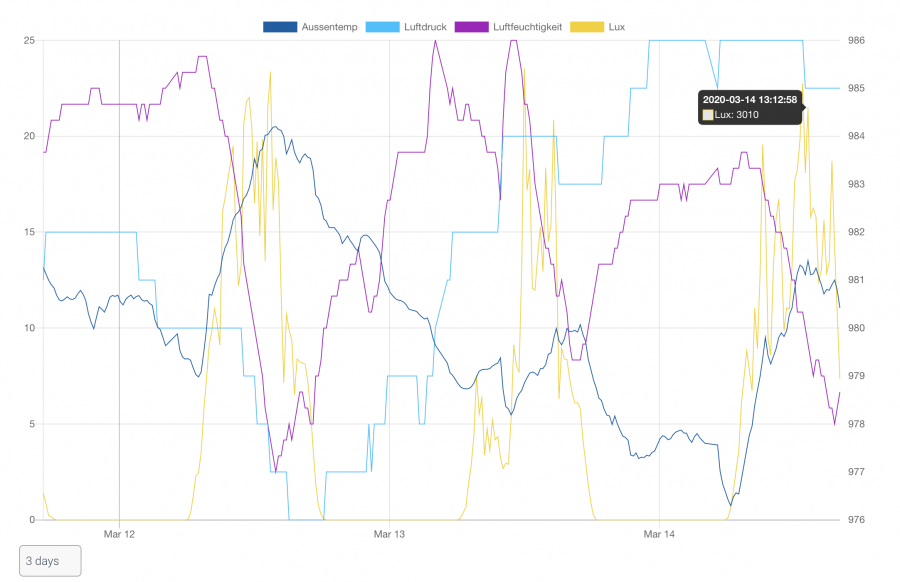
Line chart

Donut chart
Key features
- REST Enpoints
- to receive data (e.g. from IoT Device Manager)
- for an overview of hive data requested by a dedicated E-Ink display (for details see this blog post)
- Alerting
- via Monitors, e.g.
- “send an email any time a specific temperature sensor sends a temperature lower than 15 degrees
- “send an email any time a humidity sensor reports a humidity of at least 85%”
- prepared to implement web hooks
- via Watchdogs, basically act like a dead man’s switch, e.g.
- “send me an email if any beehive-scale did not send any data for two hours”
- via Monitors, e.g.
- WordPress Shortcodes for visualisation
- Generic Report Cards
- freely configurable which sensor data to show
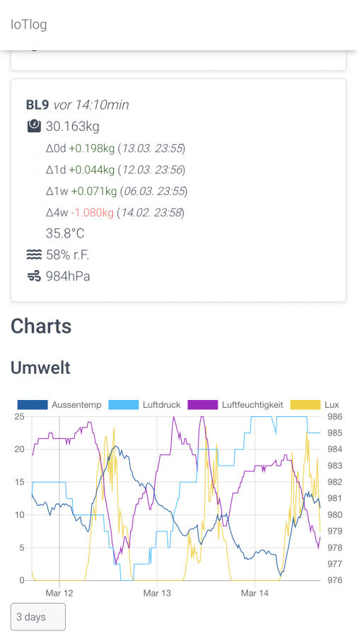
- responsive – automatically adapt view to mobile and desktop devices
- Charts
- freely configurable line and donut charts
- Generic Report Cards
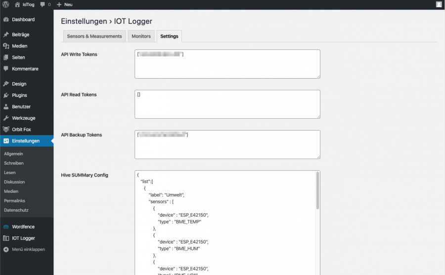
- WordPress Admin area for simple configuration

Mobile friendly data visualisation

IoTLog Admin Area – Sensors

IoTLog Admin Area – Monitors

IoTLog Admin Area – Settings
Swarm Detection

Detect swarms as they happen and don’t lose your bee colony. 

Specially for detecting swarming bee colonies I implemented a monitor that allows to send an email any time a beehive-scale reports a weight lower than 1.2kg compared to the value an hour ago. Of course the threshold and duration is customisable.
Conclusion
This is my interpretation of what a beehive-scale and/or IoT platform for personal use should look like. A big advantage for me is that I host the scripts on my own webhost and am therefore not depended by any other third-party system. Furthermore collecting data can fastly grow into privacy issues so it is always fine to know what exactly happens to your data.
Questions?
You have any more questions about my beehive-scale / IoT solution?
You need help with your own similar project?
Feel free to comment below or drop me a line via e-mail – see zeitwesentech.com for contact details.


Links
Please also check back at my fathers bees:


